KNOWLEDGE BASE
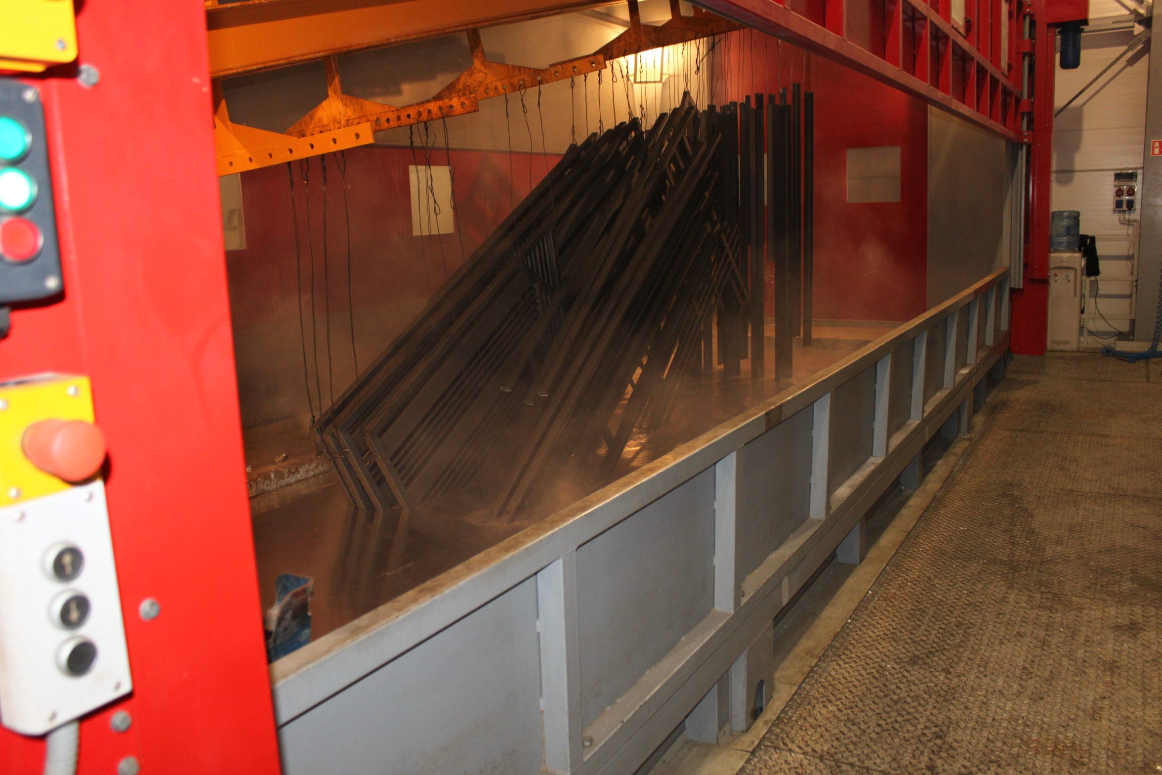
- Preparation of material for galvanizing.
– Technological holes table. (drawings, animations, description)
– Errors in the preparation of material. (photographs with description).
Requirements for hot dip galvanized structures.
– Chemical composition of steel for hot dip galvanizing
Most of the available steel grades presented in the standards can be hot dip galvanized, however the quality of the resulting zinc coating (luster, smoothness, thickness, adhesion) is different and depends on the chemical composition of the steel, in particular on the content of silicon (Si), carbon (C) and phosphorus (P). The content of silicon (Si) and carbon (C) in the steel should not exceed 0.5% in total, and the content of silicon should not be in the range from 0.03% to 0.15% and above 0.25%, because then the so-called Sandelin effect is observed – the zinc coating becomes dull-gray and rough, uneven, not very adhesive and brittle. In case the steel contains phosphorus, it is necessary to calculate the equivalent value Esi=Si+2,5xP (where Si and P represent the percentage of silicon and phosphorus in the steel). The Esi equivalent value must also meet the requirements as above for (Si). The product shall be designed so that it does not carry in its internal and external spaces the individual media of chemical treatment and zinc.
– Design of hot-dip galvanized structures
- Any internal stiffeners in the form of welded gussets stiffening the beam shall have their corners cut off and the internal corners shall be drilled for the free flow of liquid zinc.
- Inner angles in lattice structures shall be welded in such a way that free space is left between the supporting beam and the reinforcing angles to ensure free zinc flow. Such an arrangement of the structure will facilitate the zinc flow, reduce the possibility of ash accumulation on the surface and the formation of air voids, which could cause under-zincing.
- Vent and drain holes shall be provided in the pipe structures for all confined spaces by drilling holes or cutting a „V” shaped hole in the profile. Directionality of drain and vent openings shall be provided so that they are on opposite sides at the bottom and top and as close as possible to the edges of structural members.
- In closed pipe spaces, when using profile internal reinforcements in the form of welded plates, it is necessary to provide for the flow of process fluids in the corners and ensure free flow of fluids in proportion to the volume to be filled.
- In order to avoid warping and deformation on elements made of sheet metal, bends in the form of „enveloping” or embossing should be applied. Moreover, galvanizing elements should be designed as symmetrical as possible with respect to „X” and „Y” axes.
- When constructing tanks, apertures of appropriate size should be provided and correct directionality of the apertures should be ensured, and the flow of technological fluids inside the tank should be foreseen to ensure the free flow of fluids in proportion to the filled volume.
- Structural elements should preferably be made of one grade of steel.

HYDROSTAL Sp. z o.o.
ul. Ofiar Oświęcimia 78
32-620 Brzeszcze
Zakład Produkcyjny II
ul. Kolejowa
32-620 Brzeszcze
woj. małopolskie
tel. +48 32 21 11 759
fax +48 32 21 09 020